Cyclic timer with independent On Off times regulations
di Stefano Purchiaroni
 | The
application is inspired to the need of a friend who practice the Kayak
Fishing. The kept fishes have to be maintained "living" for a long
time. He built a tank, feeded using a sea water pump. In order to
regulate the water flow, he asked me to realize this timer. The circuit
is powered by a 12V or 6V battery. The ON and OFF times are managed
independently using two resistive trimmers. The circuit implements a
well known NE555 astable configuration, and may be used for any other
purpose, adapting the RC network values to the personal needs. The
Relais has to be choosen in function of the battery voltage. |

Since
early 1971, the 555 remains the most versatile timer ic. It is
possible to consult the large amount of literature online, to
understand his functions. But I would provide here a synthetical one:
At powe on, C2 ensure the internal Flip Flop reset, who brings the
output port to be High. Meanwhile, C1 begins to charge through D2 and
the R2+RV2 series. Once the 2/3 Vcc threshold is reached, the upper
comparator sets R high, making the FF to switch. At this point the
output goes Low, and the internal NPN transistor enters in conduction
state, making C1 to discharge through D1 and R1+RV1 series. The
discharge continues until the C1 voltage decreases under the 1/3 Vcc
threshold. Now the lower comparator sets S high, restoring the initial
conditions.
With
the exception of fist charge phase, that begins from 0 volts (the next
steps begins from 1/3 Vcc), the times may be calculated using the
following formulas: Ton = 0,693*C1*(R4+R2+RV2), Toff =
0,693*C1*(R1+ RV1). They can be approximated, when R4 ≪ R+RV, to
the following: T =
0,000693*C1*(1+R+RV) adopting Kohm e uF units. The table below
supplies some values to be used for times between 7 and 700 seconds.
Share the total resistance between the fixed and the variable resistors
to obtain the desired intervals. Approximate to the upper value for
commercial trimmers, to avoid intervals cutting.


In our case the values choosen for C1 and the resistors make the timer to work in the following time intervals:
Ton : 15 – 110 s
Toff : 90 – 330 s
The
proposed layout foreseen a squared 50 x 50 mm board, with holes at his
corners to mount it in a sealed box, where the power and appliance
cords have to be brought. In the next section, there are all the
pictures useful to realize the pcb. Download and print the w/b board
image that is already reflected horizonally, and arrange his size to
fit to 50 x 50 mm.
|  |


Variante
It may occurs a Relè with NO and NC pin inverted. In this case use the following layout:


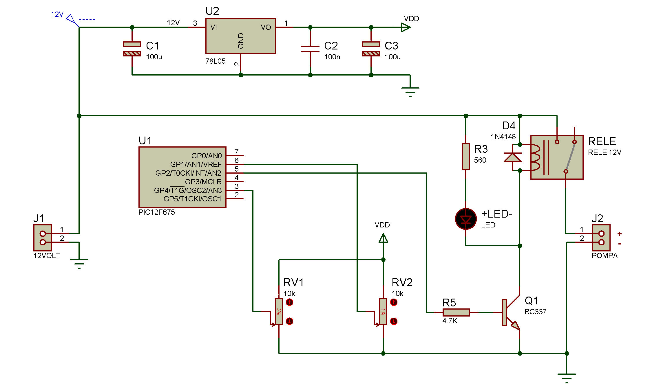
Digital version using a PIC12F675 microcontroller
This
version has no time variation due to compoennts' temperature. The
circuit adopts a microcontroller, and uses its precise internal clock
to manage the timing. The times setting occurs at every phase reading
the trimmers levels vua two 10 bit A/D channels. It makes possible to
adjust the timing during operations. The maximal times are set via code
to 2 (Ton) and 10 (Toff) minutes, but the code is supplied in order to
allow the user to change the values if needed.
The PCB has the same shape and size of the analog version making it possible to use the same container box.


The PIC12F765 mcu has to be programmed using this hex file. The code source is shown hereafter. The two constants named TonMax and ToffMax determine the maximum time for ON and OFF phases with the related trimmers all set clockwise.
/***********************************************************************************
Cyclic timer
Ton and Toff setting uses two trimmers via ADC pins. See schematic
MCU: PIC12F675
Oscillator: Internal, 4.000 MHz
Compilator: mikroC v8.2.0.0
Author: stefano.purchiaroni@email.it
Changes log:
- 03.08.2017 : Creation of the program
***********************************************************************************/
#define TonMax 120 // Max ON state time (s)
#define ToffMax 600 // Max OFF state time (s)
void SetOut(int outval, int tmax, int channel) {
// Set output according to specified value for a time got from the indicated analog channel
int i, t;
GPIO.F2 = outval;
t = ((long)Adc_Read(channel) * tmax) / 1024;
for (i=0;i<=t;i++) Delay_ms(1000);
}
void main() {
CMCON = 0b00000111; // Comparator module off
ANSEL = 0b00001010; // Configure ANalog pins (1=An)
TRISIO = 0b11111011; // Configure pins directions (0=Out)
do
{
// Endless loop
SetOut(1,TonMax,3); // Turn output on and wait Ton=AN3 seconds
SetOut(0,ToffMax,1); // Turn output off and wait Toff=AN1 seconds
} while(1);
}
Digital version with PIC12F683 and without relay for small loads
A
friend needed to time the crib's bells. So I realised this other
version employing a 12F683 and a BD139 transistor in place of the
relay. Also the trimmers are two smaller ones, to minimize pcb size to
about 2.5 centimeters side. The load shall remain under 0.5 Ampere (1 A
max, using an heat sink) and the power shall stay under 24V. Click here to download the Hex file to load on the PIC12F683.


